
Quantum Feedback Measurements
Application Description
In quantum feedback measurements, the results of single-shot qubit measurements are used as decision input for an immediate feedback action on the qubits within their coherence time. As coherence times are often short, having access to the lowest possible latency is crucial to maintain the fidelity of the overall operation as high as possible. To ensure repeatability, the entire feedback loop needs to be completed with deterministic timing even when passing through multiple instruments.
Quantum feedback is used in applications such as rapid qubit initialization, quantum state stabilization, and quantum error correction. Use cases differ in the complexity of the required signal processing between measurement and feedback; the signal processing step ranges from a simple forwarding of digital bits of information to demanding error syndrome decoding. Zurich Instruments' products cover the full range of configurations required in superconducting and spin qubit experiments to make sure that the best trade-off between feedback speed and complexity handling is achieved.
Measurement Strategies

Measurement Strategies
Event-based: 50 ns latency
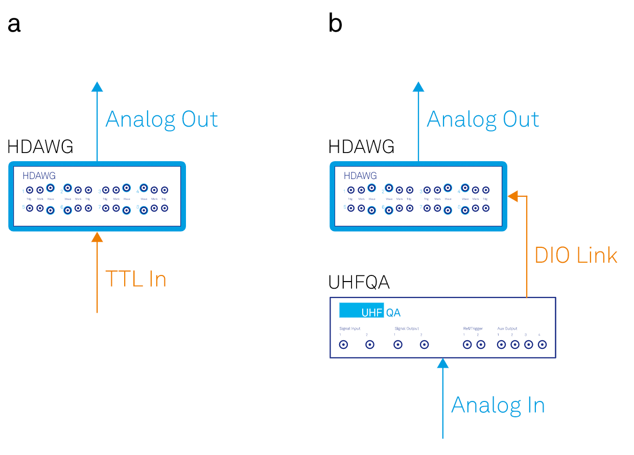
In the fastest possible configuration, a TTL rising edge is sent to one of the trigger inputs of the HDAWG to generate an analog signal (first-sample-out) on one pair of outputs 50 ns later (see panel a in the figure). This configuration is suitable when the readout signal of 1 qubit is deliberately fed back onto 1 specific qubit, as is the case in active qubit reset. The TTL signal can be supplied by third-party equipment for qubit readout.
Point-to-point: 380 ns latency
In this configuration, a UHFQA is connected through a VHDCI cable (DIO link) to an HDAWG (see panel b in the figure). The DIO link transfers up to 10 qubit readout signals as digital bits; these 10 bits of information can be used to control 8 HDAWG output signals. The latency of 380 ns is measured from the time when the last sample of a readout pulse enters the Signal Input of the UHFQA to the time when the first sample of a control pulse is generated on the Wave Output of the HDAWG. Given that the DIO link is a point-to-point connection, this configuration applies to a subset of all possible feedback options.
QCCS-enabled: 700 ns latency
As shown in the figure (panel c), multiple HDAWGs are connected through ZSync cables to a PQSC and multiple UHFQAs are connected to the HDAWGs via VHDCI cables (DIO links). Each DIO link/ZSync connection transfers up to 10 qubit readout signals from a UHFQA to the PQSC. The ZSync connection also transfers bit words from the PQSC to the HDAWG, which may be used as a decision input for waveform selection. With its feedback feature, the PQSC is able to process qubit readout data with a look-up table. On the fastest possible path, the latency between the last sample in on any UHFQA and the first sample out on any HDAWG is lower than 700 ns. This configuration is scalable to large qubits numbers in two ways: first, the star topology supports up to 18 ZSync connections. Second, the central data processing resources on the PQSC enable the implementation of syndrome decoding for quantum error correction.
The Benefits of Choosing Zurich Instruments
- Low latency, scalability, powerful real-time data processing: all critical requirements for your quantum feedback measurements are met at the same time.
- Take advantage of the flexibility to choose the optimal configuration for your experiment among the scenarios discussed above.
- You can use state-of-the-art experimental methods without the need for extensive knowledge of FPGA programming.