
Non-Contact Atomic Force Microscopy (NC-AFM)
Application Description
Non-contact atomic force microscopy (NC-AFM), also known as dynamic force microscopy (DFM), is the AFM mode that historically has achieved the highest microscopy resolution, down to sub-atomic levels, in real space. Most NC-AFM applications are performed in ultra-high vacuum (UHV) and/or in a low-temperature environment to benefit from high Q-factor sensitivity; this is especially relevant when dealing with short-range forces or atomic-scale imaging. Tracking the resonance frequency enables a faster response compared to open-loop techniques in similar conditions, and brings in the additional advantage of quantitative resonance enhancement.
From an instrumentation viewpoint, three aspects need to be considered for the highest performance with NC-AFM:
The steepest phase slope at resonance is directly related to the highest sensitivity.
NC-AFM operation works best with high-Q resonators (e.g., quartz or MEMS-based sensors) or in a vacuum environment limiting intrinsic loss.
Excellent servo loop electronics speed up relaxation.
High-Q means small resonator natural bandwidth (proportional to f/2Q). To achieve a reasonable pixel dwell time, an optimized phase-locked loop (PLL) provides the best trade-off between speed and resolution. This differs from tapping-mode or AM-AFM techniques, where the phase can vary freely and the amplitude can settle over longer time scales.
Linearizing the system gives access to quantitative, accurate measurements.
Phase and amplitude can be tracked simultaneously to provide additional information on dissipation processes. Careful tracking of the resonance ensures that amplitude measurements are always performed at the peak resonance value, thus providing maximum response and constant gain amplification for quantitative analysis.
Measurement Strategies
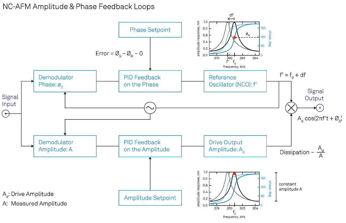
NC-AFM is often referred to as frequency-modulation AFM (FM-AFM) because of the detuning of the resonance frequency due to the tip-sample interaction. This shift of the resonance frequency is measured and tracked thanks to a PLL, while an Automatic Gain Controller (AGC) keeps the amplitude constant.
The oscillating motion of the tip reflects the convolution of the small tip-sample interaction with a robust and stable resonator: as static contributions cancel out in dynamic mode, the physical observable is the force gradient directly related to the frequency shift in the resonance. The amplitude and phase of this oscillatory motion can be measured with a lock-in detection technique and fed into two different PID loops. In NC-AFM, the PLL and AGC work together by acting on the drive frequency of the oscillator and the excitation voltage output that result in a drive signal (i.e., a physical signal output) for the mechanical resonator, as shown in the figure. The same method can be applied to optomechanical resonators and to micro-/nano-electromechanical systems (MEMS/NEMS).
The aim of the PLL and the AGC is to lock the drive signal in phase while keeping the oscillation amplitude at its peak resonance value. This separates conservative and dissipative processes, and ensures quantitative measurements. The PLL/PID option – available on the MFLI, UHFLI and HF2LI Lock-in Amplifiers – makes it possible to optimize one or multiple feedback loops thanks to simulation tools that determine P, I, and D values for a given target loop bandwidth. Indeed, the PID Advisor within the LabOne control software relies on quantitative DUT transfer function models.
While scanning, all signals available internally such as phase, amplitude, frequency, and excitation voltage can be output to analog BNC or recorded digitally with the LabOne data acquisition (DAQ) module or one of the LabOne APIs. The data can be aligned to form an image, provided some end of line trigger (EOL) or fast scan axis is fed as a trigger signal to the instrument. Multiple images can then be acquired at once, even over multiple eigenmodes or harmonics.
The Benefits of Choosing Zurich Instruments
- Don't compromise between speed and resolution: make sure that you pick the best parameters with the PID Advisor.
- You can save all internal signals digitally by synchronising the data acquisition with the scan engine thanks to the LabOne DAQ module.
- Open up to a wealth of new modes where multi-frequency and direct sideband detection can be added to your setup's capabilities.
- Improving the performance of your favorite thrid-party microscope is possible – a simple add-on is all it takes.
- The PLL/PID functionalities can be integrated into third-party software thanks to the LabOne APIs.